The Four Probe Method is one of the standard and most widely used method for the measurement of resistivity. In its useful form, the four probes are collinear. The error due to contact resistance, which is significant in the electrical measurement on semiconductors, is avoided by the use of two extra contacts (probes) between the current contacts. In this arrangement the contact resistance may all be high compare to the sample resistance, but as long as the resistance of the sample and contact resistance's are small compared with the effective resistance of the voltage measuring device (potentiometer, electrometer or electronic voltmeter), the measured value will remain unaffected. Because of pressure contacts, the arrangement is also specially useful for quick measurement on different samples or sampling different parts of the sample.
Description of the experimental set-up
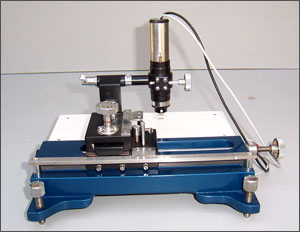
1. Probes Arrangement
It has four individually spring loaded probes. The probes are collinear and equally spaced. The probes are mounted in a teflon bush, which ensure a good electrical insulation between the probes. A teflon spacer near the tips is also provided to keep the probes at equal distance. The probe arrangement is mounted in a suitable stand, which also hold the sample plate. To ensure the correct measurement of sample temperature, the RTD is enbeded in the sample plate just below the sample. This stand also serves as the lid of temperature controlled oven. Proper leads are provided for the current and voltage measurement.
2. SAMPLE
Germanium crystal in the form of a chip.
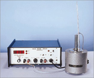
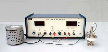
3. OVEN
This is high quality temperature controlled oven suitable for Four Probe Set-up. The oven has been designed for fast heating and cooling rates, which enhances the effectiveness of the controller.
4. FOUR PROBE SET-UP
The set-up consists of three units housed in the same cabinet.
(i) Oven Controller
Platinum RTD (A class) has been used for sensing the temperature. A wheatstone bridge and an instrumentation amplifier are used for signal conditioning. Feedback circuit ensures offset and linearity trimming and a fast accurate control of the oven temperature.
| Specifications of the Oven |
| Temperature Range |
Ambient to 473K |
| Resolution |
1K |
| Stability |
±0.5K |
| Measurement Accuracy |
±1K (typical) |
| Oven |
Specially designed for Four Probe Set-Up |
| Sensor |
RTD (A class) |
| Display |
3½ digit, 7 segment LED with autopolarity and decimal indication |
| Power |
150W |
(i) Multirange Digital Voltmeter
In this unit, intersil 3½ digit single chip A/D Converter ICL 7107 has been used. It has accuracy, auto zero to less than 10 V, zero drift-less than 1 V/ C, input bias current of 10 pA and roll over error of less than one count. Since the use of internal reference causes the degradation in performance due to internal heating, an external reference has been used.
Specifications
Range |
X1 (0-200mV) & X10 (0-2V) |
Resolution |
100V at X 1 range |
Accuracy |
0.1% of reading 1 digit |
Display |
3½ digit, 7 segment LED with autopolarity and decimal indication |
Overload Indicator |
Sign of 1 on the left & blanking of other digits. |
(ii) Constant Current Generator
It is an IC regulated current generator to provide a constant current to the outer probes irrespective of the changing resistance of the sample due to change in temperatures. The basic scheme is to use the feedback principle to limit the load current of the supply to preset maximum value. Variations in the current are achieved by a potentiometer included for that purpose. The supply is a highly regulated and practically ripple free d.c. source. The current is measured by the digital panel meter.
Specification
Open Circuit Voltage |
18 V |
Current range |
0 - 20 mA |
| Resolution |
10 A |
| Accuracy |
0.25% of the reading 1 digit |
| Load regulation |
0.05% for 0 to full load |
Line Regulation |
0.05% for 10% changes |
|